PLC Training: Exercise #2 Solution with RSLogix 5000

With those posts i will show how to use  RSLogix 5000 and Emulate 5000 to simulate a simple program.
I will also cover all the steps that are needed to realize a program with ladder logic and a simple sequence, to give a sample on how you could base your automation projects.

The text of the exercise is available here: http://www.megaupload.com/?d=PIWQA7AS

Realize the automation of the following Filling system:

Outputs:
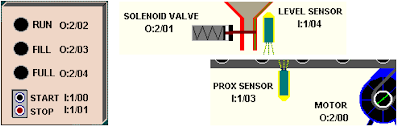
- Motor contactor (contactor O:2/0) moves the conveyor
- Solenoid valve (contactor O:2/1) to fill the boxes
- Run pilot lamp (O:2/2) activated when the machine is running
- Fill pilot lamp (O:2/3) activated when the machine is filling
- Full pilot lamp (O:2/4) activated when the box on conveyor is full

Inputs:
- Start Push button (I:0/0)
- Stop  Push Button (I:0/1)
- Prox Sensor (I:0/2) the box is in position on his right falling edge
- Level Sensor (I:0/3) the box is full when the sensor is ON
- Three-state Selector:
I:0/4 for Continous mode
I:0/5 for Manual Restart (after a box is full, this will bring the box out of level sensor and bring a new box in position)
I:0/6 for Filling bypass

You can find the various steps here:
- Process analysis: http://mestaa.blogspot.com/2011/04/plc-training-exercise-2-with-rslogix.html
- Input mapping: http://mestaa.blogspot.com/2011/04/plc-training-exercise-2-with-rslogix.html
- Writing and manage a sequence: http://mestaa.blogspot.com/2011/05/cycles.html
- Outputs Mapping:
- Simulating the process to debug the program: http://mestaa.blogspot.com/2011/05/bsimulation-in-test-driven-development.html
- Exercise file for RSLogix 5000: http://www.megaupload.com/?d=9GXL96L7

PLC Training: Exercise #2 Cycles with RSLogix 5000

You can find the other parts of the exercise here: http://mestaa.blogspot.com/2011/05/plc-training-exercise-2-solution-with.html
  

4) Cycle logic
To realize automatic cycles and sequences i often use a shift register with BSL block.
In this way it's possible to define the sequence's steps as bits, giving a comment to everyone.
In my opinion this is a clear way to read the current state of the cycle and what's happening inside.
Every cicle is made of 5 parts:
- Init (command outputs when in Stop state)
- Start (latches the 1st step)
- Stop (conditions to block the cycle and go to INIT state)
- Advance Step conditions (contains the BSL block)
- Outputs for every step (contains the commands for outputs)

In the scheme above we see that we have 3 steps + a Stop state.
Step #1: Waiting for Box in position
Step #2: Box is full
Step #3: Box is moved outside the level sensor
We can notice also that to change steps are needed some signals and that the sequence can go only one way:
Stop -> 1 -> 2 -> 3 -> 1 -> 2 ... while stop isn't pressed.
We also notice that when Start is pressed, the sequence can restart only from the 1st step, this because the exercise asks that the process must be restarted.
When working with real processes anyway can happen that the cycle step must be mantained when a user push stop for mantainence, or that the system should recognize the current state from the Inputs, so it can start an init or ending automatic sequence once restarted.

Usually i start writing my cycles from "Step Advance" and "Commands" blocks:

As you notice every step in the diagram has the same number as the step in the cycle, and for every step there is the condition for advancing in the same rung.

Commands:
 
I would like to point the attention on the use of Set/Reset coils for Motor Command.
Even if i prefere to use normal coils instead of Set/Reset, i like even more to see my steps in order from the 1st to the last one.
I know that it's possible and easy to convert the OTL and OTU into a single OTE coil, but for readability i prefere to use one rung for each step and place them in ascending order.
That's why for every output that should be energized more than once during the cycle, usually i use latch/unlatch coils.
Be careful on doing it with finite state machines, because it's easy to make error if the cycle skips the rung that resets the coil.
Notice that in the step #2 it's implemented the condition to start the motor (manual restart + PB pressed). Usually it's a good habit to put a NO contact on the top and an NC on the bottom to refere to the same condition (like Automatic / Manual selector) but here it was used a three state selector, and so i suppose to have 3 inputs.

In the end i usually write the Start - Stop - Init rungs:
As you can notice, to start the cycle it's enough to latch the 1st step, the reset request is satisfied by the cicle stop and the init must reset the commands.
Cycle is enabled by pressing of start PB and stopped by Stop PB, so i called the enable signal "Automatic Mode", so everyone can understand what's going on in the program.

5) Output Mapping
For Outputs, except pilot lamps, i separate rungs in "Automatic mode" and "not Automatic mode", using the second essentially for jogging.
In this exercise it's required the possibility to move the conveyor with a "bypass selector" that is exactly a jogging control for conveyor.(i will add the picture soon... be patient)

6) Exercise file
you can find the exercise solved for RSLogix 5000 here: http://www.megaupload.com/?d=9GXL96L7

Next part here: Simulation

PLC Training: Exercise #2 Simulation with RSLogix 5000

You can find the other parts of the exercise here: http://mestaa.blogspot.com/2011/05/plc-training-exercise-2-solution-with.html

RSEmulate Tutorial:
You can find a good tutorial for RSEmulate 5000 here: http://www.plcdev.com/a_quick_tutorial_on_rslogix_emulator_5000.
Pay attention especially in the last part where it says that for inputs you should refere to local_input[1] and for output refere to local_output[0].

7)Simulation
In test driven development usually it's a good habit to write simulation before the logic, and then test the logic while writing it.
To simulate a real plant just connect the output to inputs, designing an ideal behaviour of your plant.
For example we know that when the motor is ON the conveyor moves and the position of the box changes.
When the box is in a certain position we know also that the Prox Sensor must be ON.
So to simulate that the position increase use a DINT variable to increment when the motor is ON and to reset after a defined value (8 in my case).
Then turn ON the proximity when position is between 3 and 5.
The same can be done with the level sensor, but we have to remember that when the box is full, the level sensor remains ON until the box hasn't moved away from it.
The following is one way to simulate this process.