How to make a Sortable ObservableCollection C#

Time ago i had to implement a sortable observable collection that was able to sort its members based on different parameters.
After long and long searching i found this code, and i report it here so it can be useful for readers too.
/*
/*
 * samples:
 * //sort ascending
 * MySortableList.Sort(x => x.Name, ListSortDirection.Ascending);
 *
 * //sort descending
 * MySortableList.Sort(x => x.Name, ListSortDirection.Descending);
 */

using System;
using System.Collections.Generic;
using System.Linq;
using System.Text;
using System.Collections.ObjectModel;

namespace TestSortableCollection
{
    public class SortableObservableCollection : ObservableCollection
    {
        public void Sort(Func keySelector, System.ComponentModel.ListSortDirection direction)
        {
            switch (direction)
            {
                case System.ComponentModel.ListSortDirection.Ascending:
                    {
                        ApplySort(Items.OrderBy(keySelector));
                        break;
                    }
                case System.ComponentModel.ListSortDirection.Descending:
                    {
                        ApplySort(Items.OrderByDescending(keySelector));
                        break;
                    }
            }
        }

        public void Sort(Func keySelector, IComparer comparer)
        {
            ApplySort(Items.OrderBy(keySelector, comparer));
        }

        private void ApplySort(IEnumerable sortedItems)
        {
            var sortedItemsList = sortedItems.ToList();

            foreach (var item in sortedItemsList)
            {
                Move(IndexOf(item), sortedItemsList.IndexOf(item));
            }
        }
    }
}


Use it in this way:
public class Person
{
public string Name{get;set;}
public int Age {get;set;}
}

public class PersonCollection:SortableObservableCollection
{
public PersonCollection()
{
[...fill collection...]
this.Sort(x => x.Name, ListSortDirection.Ascending);
}
}

Multilanguage applications with C# with database support


As i wrote in an earlier post, the best way to realize a multilanguage application is to get translated text from a database.
This because even if you know 2 or 3 languages, you should be able to sell the application worldwide without even care on what language it is realized.
I think that one of the best database to use for translations is MS Access, because every translator has an office suite installed on his PC, and for him makes no difference translate on Excel or Access, but if you ask him to translate your sentences on "a random SQL data viewer", it can be a pain.
To support multilanguage in my apps i use a method that, given the name of control, returns a string containing the translated text, like:
lblSample.Content = Translation.GetString("lblSample");
The reference to the culture is contained inside Settings, and that's where i modify my language preferences, so when i load the program i know automatically what language i should use.
You can find the link for a working example at the bottom of the page.

To realize a multilanguage selection you need:
- a listbox containing the list of languages,
- an "Apply" button
Features:
- The listbox should automatically detect the new languages
- The application should change not only the texts, but also date/time format, right to left writing and so on.

1#: Create a database file with access like in the sample and add it to the project:

2#: Download the translation class from
here
and paste it in your project,
or you can download the class with the working sample here:
http://www.megaupload.com/?d=H5ISA83P

3#: Add the current culture field on "Settings": this field will be used on all the project to set the national preferences.

4#: Customize the translation class modifying the namespace and the table rererences, if you modified them.
using ChangeLanguage.Properties; // modify the namespace with your project name
[...]
//connection string
        private static DatabaseResourceManager databaseResourceManager = new DatabaseResourceManager(settings.translationsConnectionString);    // here the connection string is declared inside settings; you can declare your own here.
[...]
OleDbCommand command = new OleDbCommand("Select * From Translations"); // Here there is the reference to table name
[...]
command.CommandText = "SELECT [key], [" + language + "] " + "FROM Translations"; // Here there is another reference to table name

5#: Create the GUI like in the example:
if you use xaml you can use this code:


6# Then in the main window you can write methods to fill the language comboBox
        /// 
 Detects languages in database and fill the listbox 
        private void LoadCmbItems()
        {
            try
            {
                List cultureList = Translations.GetCultureList();
                listLanguages.ItemsSource = cultureList;
                listLanguages.SelectedItem = settings.currentCulture;
                Date = DateTime.Now;
            }
            catch (Exception exc)
            {
                MessageBox.Show(exc.Message, "Language Database error", MessageBoxButton.OK, MessageBoxImage.Error);
            }
        }
and to load / change texts (but usually i do this only on the launch of application)
        private void SetTextsInCurrentLanguage()
        {
            this.Language = XmlLanguage.GetLanguage(CultureInfo.CurrentCulture.IetfLanguageTag);
            LoadCmbItems();
            lblLanguages.Content = Translations.GetString("lblLanguages");
            btnApply.Content = Translations.GetString("btnApply");
            btnButton.Content = Translations.GetString("btnButton");
            lblLabel.Content = Translations.GetString("lblLabel");
            lblDateTime.Content = Translations.GetString("lblDateTime");
        }
You can see that it's really simple to extract translation with this method, it's just needed that you pass the name of the control to the method GetString to receice the translated Content.

7#: Once you wrote all translations, you can update the constructor of the main window to load the localized language and settings:
            Thread.CurrentThread.CurrentCulture = settings.currentCulture;
            Thread.CurrentThread.CurrentUICulture = settings.currentCulture;
            this.DataContext = this;         

            InitializeComponent();

            SetTextsInCurrentLanguage();          
and also create the button "Apply", that basically changes the settings (and in the example refresh the GUI also) :
        private void btnApply_Click(object sender, RoutedEventArgs e)
        {
            settings.currentCulture = (CultureInfo)listLanguages.SelectedItem;
            Thread.CurrentThread.CurrentCulture = settings.currentCulture;  //not so good to see... just to explain how it works
            Thread.CurrentThread.CurrentUICulture = settings.currentCulture;//you should force the user to re-initialize the program
            SetTextsInCurrentLanguage();
        }

You can download the full example here:
http://mesta-automation.com/Downloads/changeLanguage.rar
and read the full documentation here:
http://en.csharp-online.net/Localization_Like_the_Pros

Disclaimer
The sample code described herein is provided on an "as is" basis, without warranty of any kind, to the fullest extent permitted by law. Mestaa.blogspot.com does not warrant or guarantee the individual success developers may have in implementing the sample code on their development platforms or in using their own Web server configurations.

Standard colors on HMI

Dear reader, this is an old version of the article. You can find the new version on my new blog.

The lack of a standard on what colors use on HMI systems is a serious problem. After watching many applications and searching for a standard, i noticed that the most of panels' graphic pages depended on taste of the engineer that realized it.
It's not the first time that i see purple buttons, blue leds and green backgrounds.
Even if there isn't a written standard on what colors you should choose, i searched for the best ways to realize graphic page and keeps updating myself on making HMI colors as helpful as possible.
This is the standard that i use as much as i can:
  • Led : green for active, gray for inactive, red for alarm.
  • Reserve leds: gray for inactive, red for alarm/reserve.
  • Motors and valve: green for active, gray for inactive, red for alarm
  • Pipes and tanks: cyan for water, gray empty, other colors if acids or special liquids.
  • Momentary buttons: all grays and possibly with windows style and an image associated. All buttons must have a description (don't use only images, better use only description if you are forced to choose).
  • Toggle buttons: i like UP-DOWN switch levers. A button that stays pushed isn't a good way on how to represent a switch.
  • Alarm banner and log: Red (everything in red should be associated to something wrong)
  • Background: gray for numerous reasons, like it doesn't hurt eyes, no problem if there is low light of too much light, all operators are used to see gray backgrounds, gray means inactive - nothing wrong.
  • Animations: i use them only when i have to attract the attention of the operator, usually for alarms status or to pay attention at some particular operation. An abuse of animation distract the operator from it's job, so it should be for a good reason (NOT FOR A LOGO!). I don't even like to represent bottles that get filled and capped (for example), because the operator is not blind and can see what's happening inside the filling machine. A good animation can be a blinking gray-red led when it is in alarm state, a gauge that is changing value, a small alarm popup in the corner and so on... useful things anyway.
  • Pictures: use ISA symbols or schematic symbols if possible; 3D is your worst friend while representing a plant. It's important that the operator understand what's happening, not that he get fashinated.
Why gray or blue for inactive: gray means "it's all normal", is the color of the background and a color that you wouldn't pay attention. Green is the color of "go on" with semaphore, it means that a component it's running. So why to make a button green? The button will never run. Same as red for buttons: red means STOP !, DANGER! EMERGENCY SWITCH, not "finish automatic mode".
A button is a component that the operator should not pay attention at all, he just know when to push it, no need to say him "PUSH IT!". Except for Reset Alarms of course :)

I took some samples of what i think are bad screens:
Blue background with light green pipes, green and gray tanks and green valves and pumps. Definetly not a good contrast and not good pictures too.

Here pictures are better, but the contrast green on green is still bad. And on top there buttons or tag without a graphic modeling, so i can't imagine how they can help an operator.

This is what i call a useful screen.
with good contrast, not much led and the active ones in green (as you can see you notice them instantly on gray) and alarms in red.
This can be useful too, even if more complex:
Notice the good contrast for liquid levels on tank. I don't know if components are red because they are not active or in alarms (as i hope), but it's definetly a good representation.

There is a very good article about using colors, animations and setting up a Graphical User Interface; you can read it here: http://www.rollthunder.com/SoftwareThatDoesntSuck/WpfForGoodAndNotEvil.htm
Even if it's really long, i try to write his points in short:
  • First Principle: That the software that you write has zero value in and of itself. You write software for one reason and one reason only: to create value by making the user of your software happier than he would be without your software.  The only value that your software ever has or ever will have is the degree to which it increases the happiness of its users. It is extremely rare that users are willing to pay for software that decreases their overall happiness. 
  • Second Principle: That computer programs increase the happiness of users in one of two ways.  The majority of applications help a user solve a specific  problem – writing an email message or an article, buying groceries or an airplane ticket, viewing a bank statement and paying bills. The user’s only goal in using this type of program is to finish the task and get on with his life, or at least on to the next task. The faster a program converts a task from not-finished to finished, the happier the user will be.
    The second way in which a program increases a user’s happiness, less common than the first, is by putting the user into a pleasurable state that he wants to maintain as long as possible, or at least as long as it remains pleasurable, like Games.
  • Third Principle: That in neither of these cases do users want to think about the programs they are using.  At all. Ever. In the former case, they want to think about the problem they are solving: the wording of the document they are writing, or whether they have enough money to pay their bills, and which unpaid creditor would hurt them the most.  They don’t want the program to distract them from the problem they’re thinking about.  If they want to goof off and waste time, they’ll bring up Solitaire, not admire the flashing video buttons in the word processor. 
The point that i liked the most is this one: Motion attracts a user’s attention. Natural selection brutally pounded that design pattern into the human brain and visual system. Our savannah-based ancestors that noticed the twitch of the saber-tooth tiger behind the tall grass avoided being eaten and passed their attentive genes on to their descendants. The ones who didn’t notice the motion got eaten, and didn’t.  Every single user is the inheritor of roughly 13,000 generations of homo sapiens who noticed motion better than the ones who didn’t make it.
[...]
As user interface expert Jared Spool wrote of his test of a Disney web page containing an animated logo, that corporate branding icon so beloved of marketeers everywhere: “Users first tried to scroll the animation off the page, and when they couldn’t, actually covered it up with their hands so they could read the rest of the text.”

I really reccomend to check this article, is well written and with tons of examples.
And i hope you enjoyed this reading.

Example on how to write sequences with Siemens Step 7 (S7-300)

The last post with RsLogix 5000 showed how to write sequence in an understandable way with Allen Bradley PLCs. Here it is a sample for Siemens Step 7.

I will analyze the exercise #3 of learning pit, you can find the full text here:
This is the system with I/Os:

And the state machine that we have to realize is this one:
With green arrows there's the sequence that we should respect, and with black arrows the start/stop conditions.
Notice that when the cycle gets interrupted, it must restart from the last state (this means that you can't drain if you didn't heat before, and so on...); at the end of the cycle you can choose if restart the cycle to do more batches, or to stop it if the batch count is done or if the selector was in single batch position.
The sequence can be realized in this way:
You can write each step of the sequence in a word (DB4.DBW0) and pass every step with a SHL_W (equally as BSL for Allen Bradley) instruction.
If you notice, you can read every rung of the sequence as you could read a green arrow in the diagram above, like "When Step1 and High Level Sensor GO TO Step 2" and so on.
With those steps we know how to enable outputs, because in STEP 1: Fill Mixer i should enable the filling pumps, checking if the product count respects the % of product 1 and 2:
 Step 2: Heat and Mix
T1 is meant to keep the mixer running for 4 seconds after the step change, so you can mix for 4 seconds then start the drain pump.
Step 3: Drain Pump
Step 4: Increment batch count and reset product counter (because the mixer is empty)
Step 5: check product count and restart the cycle or stop it.
How to read this: in the last step of a cycle the 1st thing to do is to reset the steps of the cycle.
Then, if the selector is in Multiple batch, i check batch-count to see if i have to restart the cycle (2nd coil) or to stop the process (Reset automatic mode.)
Of course if the selector is not in multiple batch mode i should reset the automatic mode wihtout checking for anything.

To start the cycle use a segment like this:
The important part of this post is anyway the one with SHL_W, the rest is just about turning ON and OFF some outputs. I post the AWL code for the change steps sequence, just translating it from ladder, to show you how it's made.
As you can see you can write a sequence using a SLW obtaining the same (almost...) readbility as with KOP.

You can download the full exercise with simulation (to be used with PLC-SIM) here: http://www.megaupload.com/?d=83C551Y6

WPF User Controls: 7 Segment Display

7 segment displays is one of the best way to show present values in industrial programs. Operators are used to see numbers and values with  7 segment led characters, and if the operator feels comfortable with what he sees, he works better and in a more correct way.
So it's our work to make them feeling "at home" with the graphic of our programs.
To make a 7 Segment Led it's just a question of adding a custom font.
The one that i like more is NI7SEG (you can download it from here: ni7seg) or google it adding a .ttf at the end.
The code to add a Custom Font is pretty simple:

        /7SegmentLed;Component/Fonts/#NI7Seg
        
where fontfamily refers to /nameofproject;Component/font_folder/name_of_font (to be seen inside the file, not the name of the ttf file).

Then you can just create a label and apply the style:

A sample program can be found here:
http://www.mesta-automation.com/Downloads/7segmentled.rar

What features a supervision / SCADA system should contain

There are many ideas on how to make a good supervisor system and this make also a lot of confusion to engineers.
Actually HMI panels are so powerful that they can be compared to SCADA, and when i visit some clients and i see their systems, 80% of times i can't understand why they choosed an expensive SCADA package instead of a simple panel.
HMI panels are better than scada for human machine interface, as they require less time to be programmed, they can just get replaced if they get broken and they require less downtime; they doesn't require an updated Operative System and they doesn't require an OPC Server.
And most of all, they are cheaper!
With this post i don't want to make a comparison with SCADA and HMI panels, but just to point out what a supervisor system should contain, it is up to you to understand if you need a simple Panel or a complex SCADA.
So a SCADA program needs:
  1. Communication driver: can be OPC , Modbus or what else, the communication is the most important thing of those systems. It must refresh values on read at least once every second.
  2. Graphical User Interface: should contain plant schemes, motors, valves, leds, pipes, sensors' state, everything connected with the plant. It should represent all the plant status and its peculiarity, and also it should be as much dynamic as possible. This means that if you represent a motor (grey), when it runs you should represent it Green, and when it is in alarm state make it blinking grey-red.
  3. Set Points entry and Present Values visualization: to permit the configuration and troubleshooting of the plant. A good way to create set point entry is to set the value on PLC, and when you receive the refresh events from communication driver you visualize just what the PLC contains in the memory.This can be not instantaneous, but you can always see if communication is up and running.
  4. Alarm management: usually made with databases, your supervisor should contain at least an alarm banner, an alarm log and a page with active alarms.
  5. Recipes management (if needed): it's made with a database too, that contains various set points that should be transmitted once the operator select the recipe. An interface CRUD is needed for this database.
  6. Plant Control (if needed): when there are heavy algorithms to be described with PLC language, for example when recipes are complex and the supervisor controls many PLCs, you can use the PLC to control drives and motors based on high level inputs (like "go to position", "set speed") coming from SCADA. 
  7. Data logging: based on database too, with a SCADA you should log all the critical process variables (pressures - temperatures - speeds and so on) and visualize them in charts like (x -> time ; y -> Set Point and Present Value and Max Threshold  + Min Threshold).
  8. Production tracking: while a product is being made, it should be associated with all the process variables' values during it's making time. This will create a database containing all the statistics needed to analyze the production and improve quality and times.
  9. Reporting: if you give data about production, you should also give to clients a way to use those data. You can show them with reports and you can also analyze them with special recipes to check for production flaws automatically.
  10. Multilanguage support: if you are going to sell the software worldwide you need to support all messages and labels with a language database (in this case an Access file is the best choice, because EVERYONE know how to compile Access tables).
Scada are systems very powerful and expensive (in working hours or in money spent to buy all packages),but it's good to see them running once you made them :)

PLC Training: Exercise #2 Solution with RSLogix 5000

With those posts i will show how to use  RSLogix 5000 and Emulate 5000 to simulate a simple program.
I will also cover all the steps that are needed to realize a program with ladder logic and a simple sequence, to give a sample on how you could base your automation projects.

The text of the exercise is available here: http://www.megaupload.com/?d=PIWQA7AS

Realize the automation of the following Filling system:

Outputs:
- Motor contactor (contactor O:2/0) moves the conveyor
- Solenoid valve (contactor O:2/1) to fill the boxes
- Run pilot lamp (O:2/2) activated when the machine is running
- Fill pilot lamp (O:2/3) activated when the machine is filling
- Full pilot lamp (O:2/4) activated when the box on conveyor is full

Inputs:
- Start Push button (I:0/0)
- Stop  Push Button (I:0/1)
- Prox Sensor (I:0/2) the box is in position on his right falling edge
- Level Sensor (I:0/3) the box is full when the sensor is ON
- Three-state Selector:
I:0/4 for Continous mode
I:0/5 for Manual Restart (after a box is full, this will bring the box out of level sensor and bring a new box in position)
I:0/6 for Filling bypass

You can find the various steps here:
- Process analysis: http://mestaa.blogspot.com/2011/04/plc-training-exercise-2-with-rslogix.html
- Input mapping: http://mestaa.blogspot.com/2011/04/plc-training-exercise-2-with-rslogix.html
- Writing and manage a sequence: http://mestaa.blogspot.com/2011/05/cycles.html
- Outputs Mapping:
- Simulating the process to debug the program: http://mestaa.blogspot.com/2011/05/bsimulation-in-test-driven-development.html
- Exercise file for RSLogix 5000: http://www.megaupload.com/?d=9GXL96L7

PLC Training: Exercise #2 Cycles with RSLogix 5000

You can find the other parts of the exercise here: http://mestaa.blogspot.com/2011/05/plc-training-exercise-2-solution-with.html
  

4) Cycle logic
To realize automatic cycles and sequences i often use a shift register with BSL block.
In this way it's possible to define the sequence's steps as bits, giving a comment to everyone.
In my opinion this is a clear way to read the current state of the cycle and what's happening inside.
Every cicle is made of 5 parts:
- Init (command outputs when in Stop state)
- Start (latches the 1st step)
- Stop (conditions to block the cycle and go to INIT state)
- Advance Step conditions (contains the BSL block)
- Outputs for every step (contains the commands for outputs)

In the scheme above we see that we have 3 steps + a Stop state.
Step #1: Waiting for Box in position
Step #2: Box is full
Step #3: Box is moved outside the level sensor
We can notice also that to change steps are needed some signals and that the sequence can go only one way:
Stop -> 1 -> 2 -> 3 -> 1 -> 2 ... while stop isn't pressed.
We also notice that when Start is pressed, the sequence can restart only from the 1st step, this because the exercise asks that the process must be restarted.
When working with real processes anyway can happen that the cycle step must be mantained when a user push stop for mantainence, or that the system should recognize the current state from the Inputs, so it can start an init or ending automatic sequence once restarted.

Usually i start writing my cycles from "Step Advance" and "Commands" blocks:

As you notice every step in the diagram has the same number as the step in the cycle, and for every step there is the condition for advancing in the same rung.

Commands:
 
I would like to point the attention on the use of Set/Reset coils for Motor Command.
Even if i prefere to use normal coils instead of Set/Reset, i like even more to see my steps in order from the 1st to the last one.
I know that it's possible and easy to convert the OTL and OTU into a single OTE coil, but for readability i prefere to use one rung for each step and place them in ascending order.
That's why for every output that should be energized more than once during the cycle, usually i use latch/unlatch coils.
Be careful on doing it with finite state machines, because it's easy to make error if the cycle skips the rung that resets the coil.
Notice that in the step #2 it's implemented the condition to start the motor (manual restart + PB pressed). Usually it's a good habit to put a NO contact on the top and an NC on the bottom to refere to the same condition (like Automatic / Manual selector) but here it was used a three state selector, and so i suppose to have 3 inputs.

In the end i usually write the Start - Stop - Init rungs:
As you can notice, to start the cycle it's enough to latch the 1st step, the reset request is satisfied by the cicle stop and the init must reset the commands.
Cycle is enabled by pressing of start PB and stopped by Stop PB, so i called the enable signal "Automatic Mode", so everyone can understand what's going on in the program.

5) Output Mapping
For Outputs, except pilot lamps, i separate rungs in "Automatic mode" and "not Automatic mode", using the second essentially for jogging.
In this exercise it's required the possibility to move the conveyor with a "bypass selector" that is exactly a jogging control for conveyor.(i will add the picture soon... be patient)

6) Exercise file
you can find the exercise solved for RSLogix 5000 here: http://www.megaupload.com/?d=9GXL96L7

Next part here: Simulation

PLC Training: Exercise #2 Simulation with RSLogix 5000

You can find the other parts of the exercise here: http://mestaa.blogspot.com/2011/05/plc-training-exercise-2-solution-with.html

RSEmulate Tutorial:
You can find a good tutorial for RSEmulate 5000 here: http://www.plcdev.com/a_quick_tutorial_on_rslogix_emulator_5000.
Pay attention especially in the last part where it says that for inputs you should refere to local_input[1] and for output refere to local_output[0].

7)Simulation
In test driven development usually it's a good habit to write simulation before the logic, and then test the logic while writing it.
To simulate a real plant just connect the output to inputs, designing an ideal behaviour of your plant.
For example we know that when the motor is ON the conveyor moves and the position of the box changes.
When the box is in a certain position we know also that the Prox Sensor must be ON.
So to simulate that the position increase use a DINT variable to increment when the motor is ON and to reset after a defined value (8 in my case).
Then turn ON the proximity when position is between 3 and 5.
The same can be done with the level sensor, but we have to remember that when the box is full, the level sensor remains ON until the box hasn't moved away from it.
The following is one way to simulate this process.

PLC Training: Exercise #2 Input Mapping

You can find the other parts of the exercise here: http://mestaa.blogspot.com/2011/05/plc-training-exercise-2-solution-with.html
 
1) Sequence analisys and algorithym

Step #1: Waiting for Box in position
Step #2: Box is full
Step #3: Box is moved outside the level sensor
To change steps follow the arrow and the signal that has to be received.
From all steps you must be able to stop the machine if Stop push button is pressed
If the machine is stopped, pressing Start push button will restart the cycle from Step #1

2) Writing the program:
Defining tasks:

those 3 tasks should be in every program
-Simulation
-Map Inputs
-Map Outputs
- There should be an Alarm task also, but in this exercise alarms are not requested.
I gave the name MainProgram to the task that runs the cycle because this is a really simple program, with one short cycle and a start/stop without particular requests.

3)Input Mapping:

I usually map inputs in DINT variables, so i can force them without problems while debugging on the real plant.
Also it makes it easy to change a broken Input without having to change all the program.
Other programmers uses to map Input in UDT data types, with all the problems connected on the  debugging phase the real system when it is ready.

As for the output i usually write an alias tag, because i always use outputs once in all program and with a coil segment.

Next part is here: Cycles and Outputs

PLC Training: Some interesting exercises

I found some interesting exercises about plc programming that cover almost all the topics that a programmer should know.
The document is mainly thought for Allen Bradley plcs users, but it can be useful also for others.
The exercises are:
1) Using simple relays logic to control a motor
2) Using relays logic to control simple sequences
3) Using Timers, Retentive Timers and Counters
4) Using relays logic + everything saw before to control a batch mixing system
5) Using shift registers to determine the position of a bottle in a filling plant
6) Using various modules to control an elevator system.

The pdf  was found on http://thelearningpit.com/lp/logixpro.html, they also sells some kind of graphical simulation to run the plants if you're interested.
 I reccomend to try logixpro simulator (15 days trial) because it can really improve your ladder code with just your time.
You can download the exercise file directly from learning pit website or from here:
http://www.megaupload.com/?d=PIWQA7AS

HMI Controls for WPF: Led (and a tutorial on WPF User Control)

You can downlaod the source code with sample here: http://www.mesta-automation.com/Downloads/Led%20Wpf.rar

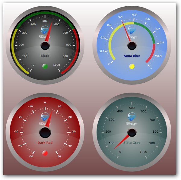
Every Scada system has his own framework that contains a lot of graphic objects, from gauges to charts, that can be controlled directly by some Tags or variables.
Unfortunately .Net doesn't come with this objects, so we have to create them.
In this sample i show how to create a simple graphical Led.

Create a new Control Library (File -> New -> Project -> WPF User Control Library),
then create a new project to test the control( to test and show how to use the control).
After the creation of this 2 projects, set the test project as startup project and add as reference the  control library.
Now we are ready to start creating the graphic part.

Basically a led can be drawn as a Border object that inside it contains a color, and his background is of another color.
This is the code for the graphic part
<Grid x:Name="gridBigLed" >
        <Border x:Name="border1" BorderThickness="6" Width="{Binding ActualHeight, ElementName=gridBigLed, Mode=OneWay}" CornerRadius="{Binding ActualWidth, ElementName=gridBigLed, Mode=OneWay}">
            <Border.Background>
                <RadialGradientBrush >
                    <GradientStop Color="White"/>
                    <GradientStop x:Name="backgroundColor" Color="Red" Offset="0.835"/>
                </RadialGradientBrush>
            </Border.Background>
            <Border.BorderBrush>
                <RadialGradientBrush>
                    <GradientStop Color="#FF020202" Offset="0.383"/>
                    <GradientStop Color="#FFE4E4E4" Offset="1"/>
                </RadialGradientBrush>
            </Border.BorderBrush>
        </Border>
    </Grid>


We bind the height of the border to the height of the grid, so we can resize the control when developing our application.
Corner radius is in binding with width too, to be sure that the border will be always circular.
For the background color you can use wathever you like. I used a radial gradient with Red(Off state) and White , and i will change it with green and  white (On state) depending on the state of a property. That's why I gave the name "backgroundColor" on the red GradientStop.

To give properties to a UserControl we must use Dependency Properties.
We will give 3 properties to the user control:
- bool IsActive
- Color ColorOn (color when IsActive is true)
- Color ColorOff (color when IsActive is false)

The declaration is the following:

/// <summary>Dependency property to Get/Set the current IsActive (True/False)</summary>
        public static readonly DependencyProperty IsActiveProperty =
            DependencyProperty.Register("IsActive", typeof(bool), typeof(Led),// null);
                new PropertyMetadata(new PropertyChangedCallback(Led.IsActivePropertyChanced)));

        /// <summary>Dependency property to Get/Set Color when IsActive is true</summary>
        public static readonly DependencyProperty ColorOnProperty =
            DependencyProperty.Register("ColorOn", typeof(Color), typeof(Led), //null);
                new PropertyMetadata(Colors.Green,new PropertyChangedCallback(Led.OnColorOnPropertyChanged)));

        /// <summary>Dependency property to Get/Set Color when IsActive is false</summary>
        public static readonly DependencyProperty ColorOffProperty =
            DependencyProperty.Register("ColorOff", typeof(Color), typeof(Led),// null);
                new PropertyMetadata(Colors.Red,new PropertyChangedCallback(Led.OnColorOffPropertyChanged)));

        /// <summary>Gets/Sets Value</summary>
        public bool IsActive
        {
            get { return (bool)GetValue(IsActiveProperty); }
            set 
            {
                SetValue(IsActiveProperty, value);
            }
        }

        /// <summary>Gets/Sets Color when led is True</summary>
        public Color ColorOn
        {
            get
            {
                return (Color)GetValue(ColorOnProperty);
            }
            set
            {
                SetValue(ColorOnProperty, value);
            }
        }

        /// <summary>Gets/Sets Color when led is False</summary>
        public Color ColorOff
        {
            get
            {
                return (Color)GetValue(ColorOffProperty);
            }
            set
            {
                SetValue(ColorOffProperty, value);
            }
        }

Now there is a lot to talk about dependency properties, but basically:
you can set the starting value when you create the objects (ColorOn starts with Color.Green and ColorOff start with Color.Red)
and you should note that every property has is name written as string in the 1st field of DependencyProperty.Register method.
the properties also access to values contained in dependency properties  by getValue() and SetValue().

Every Dependency Property should have is own method when it changes. Those methods describe the behaviour of our object, basically a change of IsActive should modify the color of the border and if i change a color at runtime, depending on the state, it should refresh the color instantly.
In this case i wrote the following methods:

private static void IsActivePropertyChanced(DependencyObject d, DependencyPropertyChangedEventArgs e) 
        {
            Led led = (Led)d;
            if ((bool)e.NewValue)
                led.backgroundColor.Color = led.ColorOn;
            else
                led.backgroundColor.Color = led.ColorOff;
        }

        private static void OnColorOnPropertyChanged(DependencyObject d, DependencyPropertyChangedEventArgs e)
        {
            Led led = (Led)d;
            led.ColorOn = (Color)e.NewValue;
            if (led.IsActive)
                led.backgroundColor.Color = led.ColorOn;
            else
                led.backgroundColor.Color = led.ColorOff;
        }

        private static void OnColorOffPropertyChanged(DependencyObject d, DependencyPropertyChangedEventArgs e)
        {
            Led led = (Led)d;
            led.ColorOff = (Color)e.NewValue;
            if (led.IsActive)
                led.backgroundColor.Color = led.ColorOn;
            else
                led.backgroundColor.Color = led.ColorOff;
        }

Note that every method is static and it access to the user control property by casting the dependencyobject d.

As for the constructor, i wrote a refresh depending on what color it's set.

public Led()
{
   InitializeComponent();
   if (this.IsActive)
       this.backgroundColor.Color = ColorOn;
   else
       this.backgroundColor.Color = ColorOff;       
}


In this way our control should work.

Now to test we should try it with and without databinding.
This is the test that i wrote:

<Window x:Class="LedTest.MainWindow"
        xmlns="http://schemas.microsoft.com/winfx/2006/xaml/presentation"
        xmlns:x="http://schemas.microsoft.com/winfx/2006/xaml"
        xmlns:uc="clr-namespace:LedControl;assembly=LedControl"
        Title="MainWindow" Height="350" Width="525">
    <Grid>
        <Grid.RowDefinitions>
            <RowDefinition Height="Auto" />
            <RowDefinition Height="10"/>
            <RowDefinition Height="Auto" />
            <RowDefinition />
        </Grid.RowDefinitions>
        <Grid.ColumnDefinitions>
            <ColumnDefinition Width="Auto" />
            <ColumnDefinition Width="Auto"/>
            <ColumnDefinition />
        </Grid.ColumnDefinitions>
        <uc:Led Name="led1" Height="60" Width="60" IsActive="False" Flashing="False" FlashingPeriod="500"  />
        <TextBlock Grid.Column="1">Led without binding</TextBlock>
        <Button Name="btnChange"  Grid.Column="2"  Content="Change" Click="btnChange_Click" />
        <uc:Led Name="led2" Grid.Row="2" Height="60" Width="60" IsActive="{Binding LedStatus}"  />
        <TextBlock  Grid.Row="2" Grid.Column="1">Led with binding</TextBlock>
        <Button Name="btnChange2"  Grid.Row="2" Grid.Column="2"  Content="Change" Click="btnChange2_Click" />
    </Grid>
</Window>


public partial class MainWindow : Window,INotifyPropertyChanged
    {
        bool ledStatus;
        public bool LedStatus
        { get { return ledStatus; } set { ledStatus = value; this.OnPropertyChanged("LedStatus"); } }

        public MainWindow()
        {
            InitializeComponent();
            led2.DataContext = this;
            led1.ColorOn = Colors.Blue;
            led1.ColorOff = Colors.Gray;
        }

        private void btnChange_Click(object sender, RoutedEventArgs e)
        {
            led1.IsActive = !led1.IsActive;
        }

        private void btnChange2_Click(object sender, RoutedEventArgs e)
        {
            LedStatus = !LedStatus;
        }


        #region INotifyPropertyChanged members

        public event PropertyChangedEventHandler PropertyChanged;
        protected void OnPropertyChanged(string propertyName)
        {
            if (PropertyChanged != null)
                this.PropertyChanged(this, new System.ComponentModel.PropertyChangedEventArgs(propertyName));
        }

        #endregion  

The 1st button test the led by changing the color from codebehind, the second test it in binding with a property contained (in this case) in the mainwindow directly.

Playing with Blend and adding more Dependency Properties will give even a better result.

Sample App is here: http://www.mesta-automation.com/Downloads/Led%20Wpf.rar

HMI Controls for Winforms: Gauge

Even if i don't like to talk about Winforms, i found a good gauge and i used for 1-2 projects:

The main page for this control and the discussion is here:
http://www.codeproject.com/KB/miscctrl/ThermometerControl.aspx
I add a project for download so you can check the source code and how to use this(it's really simple).

http://www.megaupload.com/?d=TVK7D9M9 

HMI Controls for WPF: Gauge

[Check the updated post here: http://www.mesta-automation.com/wpf-gauge-with-samples/]

Most of times the Gauge indicator is used in HMI projects to visualize Speed - Pressure - Temperatures and so on.
I also prefere using Gause against other tipes of controls such as thermometers, bar graph and others, becuase the measure it's clear and the minimum, maximum and alarm threshold are evidents.
In WPF there are 2 kind of free gauges with free source code:
1) http://wpfgauge.codeplex.com/


this is a free gauge that has no animations (and it can be good ) but it's under the LGPL license, so this means that the code using this gauge must be GPL - licensed.

2) http://www.codeproject.com/KB/silverlight/circulargaugecontrol.aspx?msg=3745697#xx3745697xx
This one is the one that i prefere. It's BSD License (so you can use it basically everywhere) and it is for both Silverlight and WPF.
It's not autosizing and that's a pity, and to dimension it you have to play with some controls.
But anyway it's a great control with a threshold indicator and easy parameters to play around.
It's easy to change colors and sizes of scale and numbers, so it can become a manomether, a thermometer and a tachimeter depending on what application you are working on.

The project can be downloaded from the original site or here:

http://www.megaupload.com/?d=5TMUYC9A


WPF Control: Listbox of checkbox with Search google-like

One thing that i like of WPF is the possibility of making easy-to-use controls to manage data.
A control that i use a lot of times to filter dataviews, charts, get queryes parameters and so on is a listbox of checkbox.
This isn't that special, but with ICollectionView and the possibility of having a fast way to filter results like the search box in google.com it become a really powerful tool.

I invite you to download the demo (link at the bottom of this page) to understand better.

Let's start from an example:
I have an observable collection of "Fruits", objects that contain a property "Name" and a property "Show" that indicates if the object has to be visualized or filtered.

To filter this collection i can use the ICollectionView, that permits to filter a collection and has a method Refresh() that reload the collection with the filter parameters.

So in the properties i add:
 class MyFruitCollection : ObservableCollection
    {

private ICollectionView filteredCollection;
public ICollectionView FilteredCollection { get { return filteredCollection; } }


and the filter string:

private string filter = "";
        public string Filter
        {
            get { return this.filter.ToUpperInvariant(); }
            set
            {
                if (this.filter != value)
                {
                    this.filter = value;
                    this.filteredCollection.Refresh(); //
Notice that i call Refresh() at every change of filter
                }
            }
        }


In the constructor of my collection i add some fruits(just for example) and i load the ICollectionView datasource:

        public MyFruitCollection()
        {
            this.Add(new MyFruit("Orange"));
            ...
            this.Add(new MyFruit("Watermelon"));

            this.filteredCollection = CollectionViewSource.GetDefaultView(this);
            this.filteredCollection.Filter = ContainsFilter;
        }

Then i set the filters on this method:

private bool ContainsFilter(object item)
        {
            var fruit = item as MyFruit;
            if (fruit == null)  //check if fruit is null
            {
                return false;
            }
            if (string.IsNullOrEmpty(this.Filter)) //check if search box is empty or null
            {
                return true; //show all items if there is no text in the search textbox
            }
            if (fruit.Name.ToUpperInvariant().Contains(this.Filter))
//checks if fruit.name contains the search text
            {
                return true;
            }
            return false; //if it doesn't contain anything don't show the item
        }


 Xaml is pretty simple, as usual it's all about databinding:

And this is the code behind:

    public partial class MainWindow : Window
    {

MyFruitCollection fruitCollection = new MyFruitCollection();

        public MainWindow()
        {
            InitializeComponent();
            this.DataContext = fruitCollection;
//notice that all the application is in binding
        }

...
}

The resul is pretty cool and it makes apps a lot more confortable, just try yourself :)
Download the example here:
http://mesta-automation.com/Downloads/Selection%20control.rar

A good (free) set of 240 icons

A big problem and a big waste of time for a programmer is the research of icons and images to associate to buttons, panels, toolbars and so on.
I really hated to do that with Google image-finder, so i searched a lot until i found a site that contained a million of icons.
Of course it can't exist that for every program i search in a database containing so many designs, so i want to show you a set of icons that in my opinion cover almost all that a programmer needs.
As usual remember that an icon should HELP the operator, not just be pretty. If you feel that the icon is not so meaningful, it's better to remove it and just leave text on the button (so the operator is forced to read it).
This is a small (and almost useless) preview of the set, that contains more useful icons for sure:

But i invite you to visit this page: http://www.iconarchive.com/category/application/aesthetica-2-icons-by-dryicons.html to see the complete set (that is really big, around 240 icons).
I want to point the attention on some icons:
- Accept, Add, Remove and Edit are pretty straightforward. I think that no one can do confusion with this set of icons.
- Back, Next, Down and Top are pretty useful too, even if i don't like to abuse of them because they are not always understandable if the context is not well defined.
- Info, Help, Search and Warning are awesome. It's impossible to don't understand what they means and they are similar to windows ones too.
- Lock - Unlock icons for password login is always useful.
- Charts, Folders, Databases, Home, Word and Calendar got always a use in programs, and they are included too.

The rest is quite trashy, or not so useful, but it always depends on what you are doing.
I really invite you to check out this set, downloadable from the bottom of this page:
http://www.iconarchive.com/category/application/aesthetica-2-icons-by-dryicons.html
selecting Linux (.png) files included (so you get the version with the set of 16x16 - 32x32 - 48x48 - 64x64 - 128x128 pixels)
Remember that if you use them you should read carefully the license, that permit a free use of this set, and to respect the work of this guys.