The last post with RsLogix 5000 showed how to write sequence in an understandable way with Allen Bradley PLCs. Here it is a sample for Siemens Step 7.
I will analyze the exercise #3 of learning pit, you can find the full text here:
And the state machine that we have to realize is this one:
With green arrows there's the sequence that we should respect, and with black arrows the start/stop conditions.
Notice that when the cycle gets interrupted, it must restart from the last state (this means that you can't drain if you didn't heat before, and so on...); at the end of the cycle you can choose if restart the cycle to do more batches, or to stop it if the batch count is done or if the selector was in single batch position.
The sequence can be realized in this way:
You can write each step of the sequence in a word (DB4.DBW0) and pass every step with a SHL_W (equally as BSL for Allen Bradley) instruction.
If you notice, you can read every rung of the sequence as you could read a green arrow in the diagram above, like "When Step1 and High Level Sensor GO TO Step 2" and so on.
With those steps we know how to enable outputs, because in STEP 1: Fill Mixer i should enable the filling pumps, checking if the product count respects the % of product 1 and 2:
Step 2: Heat and Mix
I will analyze the exercise #3 of learning pit, you can find the full text here:
This is the system with I/Os:
And the state machine that we have to realize is this one:
With green arrows there's the sequence that we should respect, and with black arrows the start/stop conditions.
Notice that when the cycle gets interrupted, it must restart from the last state (this means that you can't drain if you didn't heat before, and so on...); at the end of the cycle you can choose if restart the cycle to do more batches, or to stop it if the batch count is done or if the selector was in single batch position.
The sequence can be realized in this way:
You can write each step of the sequence in a word (DB4.DBW0) and pass every step with a SHL_W (equally as BSL for Allen Bradley) instruction.
If you notice, you can read every rung of the sequence as you could read a green arrow in the diagram above, like "When Step1 and High Level Sensor GO TO Step 2" and so on.
With those steps we know how to enable outputs, because in STEP 1: Fill Mixer i should enable the filling pumps, checking if the product count respects the % of product 1 and 2:
Step 2: Heat and Mix
T1 is meant to keep the mixer running for 4 seconds after the step change, so you can mix for 4 seconds then start the drain pump.
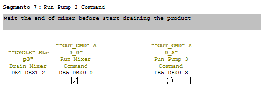
Step 3: Drain Pump
Step 4: Increment batch count and reset product counter (because the mixer is empty)
Step 5: check product count and restart the cycle or stop it.
How to read this: in the last step of a cycle the 1st thing to do is to reset the steps of the cycle.
Then, if the selector is in Multiple batch, i check batch-count to see if i have to restart the cycle (2nd coil) or to stop the process (Reset automatic mode.)
Of course if the selector is not in multiple batch mode i should reset the automatic mode wihtout checking for anything.
To start the cycle use a segment like this:
The important part of this post is anyway the one with SHL_W, the rest is just about turning ON and OFF some outputs. I post the AWL code for the change steps sequence, just translating it from ladder, to show you how it's made.
As you can see you can write a sequence using a SLW obtaining the same (almost...) readbility as with KOP.
You can download the full exercise with simulation (to be used with PLC-SIM) here: http://www.megaupload.com/?d=83C551Y6


No comments:
Post a Comment