Showing posts with label simulators. Show all posts

Example on how to write sequences with Siemens Step 7 (S7-300)

The last post with RsLogix 5000 showed how to write sequence in an understandable way with Allen Bradley PLCs. Here it is a sample for Siemens Step 7.

I will analyze the exercise #3 of learning pit, you can find the full text here:
This is the system with I/Os:

And the state machine that we have to realize is this one:
With green arrows there's the sequence that we should respect, and with black arrows the start/stop conditions.
Notice that when the cycle gets interrupted, it must restart from the last state (this means that you can't drain if you didn't heat before, and so on...); at the end of the cycle you can choose if restart the cycle to do more batches, or to stop it if the batch count is done or if the selector was in single batch position.
The sequence can be realized in this way:
You can write each step of the sequence in a word (DB4.DBW0) and pass every step with a SHL_W (equally as BSL for Allen Bradley) instruction.
If you notice, you can read every rung of the sequence as you could read a green arrow in the diagram above, like "When Step1 and High Level Sensor GO TO Step 2" and so on.
With those steps we know how to enable outputs, because in STEP 1: Fill Mixer i should enable the filling pumps, checking if the product count respects the % of product 1 and 2:
 Step 2: Heat and Mix
T1 is meant to keep the mixer running for 4 seconds after the step change, so you can mix for 4 seconds then start the drain pump.
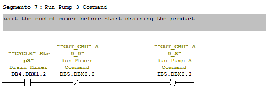
Step 3: Drain Pump
Step 4: Increment batch count and reset product counter (because the mixer is empty)
Step 5: check product count and restart the cycle or stop it.
How to read this: in the last step of a cycle the 1st thing to do is to reset the steps of the cycle.
Then, if the selector is in Multiple batch, i check batch-count to see if i have to restart the cycle (2nd coil) or to stop the process (Reset automatic mode.)
Of course if the selector is not in multiple batch mode i should reset the automatic mode wihtout checking for anything.

To start the cycle use a segment like this:
The important part of this post is anyway the one with SHL_W, the rest is just about turning ON and OFF some outputs. I post the AWL code for the change steps sequence, just translating it from ladder, to show you how it's made.
As you can see you can write a sequence using a SLW obtaining the same (almost...) readbility as with KOP.

You can download the full exercise with simulation (to be used with PLC-SIM) here: http://www.megaupload.com/?d=83C551Y6

PLC Training: Exercise #2 Cycles with RSLogix 5000

You can find the other parts of the exercise here: http://mestaa.blogspot.com/2011/05/plc-training-exercise-2-solution-with.html
  

4) Cycle logic
To realize automatic cycles and sequences i often use a shift register with BSL block.
In this way it's possible to define the sequence's steps as bits, giving a comment to everyone.
In my opinion this is a clear way to read the current state of the cycle and what's happening inside.
Every cicle is made of 5 parts:
- Init (command outputs when in Stop state)
- Start (latches the 1st step)
- Stop (conditions to block the cycle and go to INIT state)
- Advance Step conditions (contains the BSL block)
- Outputs for every step (contains the commands for outputs)

In the scheme above we see that we have 3 steps + a Stop state.
Step #1: Waiting for Box in position
Step #2: Box is full
Step #3: Box is moved outside the level sensor
We can notice also that to change steps are needed some signals and that the sequence can go only one way:
Stop -> 1 -> 2 -> 3 -> 1 -> 2 ... while stop isn't pressed.
We also notice that when Start is pressed, the sequence can restart only from the 1st step, this because the exercise asks that the process must be restarted.
When working with real processes anyway can happen that the cycle step must be mantained when a user push stop for mantainence, or that the system should recognize the current state from the Inputs, so it can start an init or ending automatic sequence once restarted.

Usually i start writing my cycles from "Step Advance" and "Commands" blocks:

As you notice every step in the diagram has the same number as the step in the cycle, and for every step there is the condition for advancing in the same rung.

Commands:
 
I would like to point the attention on the use of Set/Reset coils for Motor Command.
Even if i prefere to use normal coils instead of Set/Reset, i like even more to see my steps in order from the 1st to the last one.
I know that it's possible and easy to convert the OTL and OTU into a single OTE coil, but for readability i prefere to use one rung for each step and place them in ascending order.
That's why for every output that should be energized more than once during the cycle, usually i use latch/unlatch coils.
Be careful on doing it with finite state machines, because it's easy to make error if the cycle skips the rung that resets the coil.
Notice that in the step #2 it's implemented the condition to start the motor (manual restart + PB pressed). Usually it's a good habit to put a NO contact on the top and an NC on the bottom to refere to the same condition (like Automatic / Manual selector) but here it was used a three state selector, and so i suppose to have 3 inputs.

In the end i usually write the Start - Stop - Init rungs:
As you can notice, to start the cycle it's enough to latch the 1st step, the reset request is satisfied by the cicle stop and the init must reset the commands.
Cycle is enabled by pressing of start PB and stopped by Stop PB, so i called the enable signal "Automatic Mode", so everyone can understand what's going on in the program.

5) Output Mapping
For Outputs, except pilot lamps, i separate rungs in "Automatic mode" and "not Automatic mode", using the second essentially for jogging.
In this exercise it's required the possibility to move the conveyor with a "bypass selector" that is exactly a jogging control for conveyor.(i will add the picture soon... be patient)

6) Exercise file
you can find the exercise solved for RSLogix 5000 here: http://www.megaupload.com/?d=9GXL96L7

Next part here: Simulation

PLC Training: Exercise #2 Simulation with RSLogix 5000

You can find the other parts of the exercise here: http://mestaa.blogspot.com/2011/05/plc-training-exercise-2-solution-with.html

RSEmulate Tutorial:
You can find a good tutorial for RSEmulate 5000 here: http://www.plcdev.com/a_quick_tutorial_on_rslogix_emulator_5000.
Pay attention especially in the last part where it says that for inputs you should refere to local_input[1] and for output refere to local_output[0].

7)Simulation
In test driven development usually it's a good habit to write simulation before the logic, and then test the logic while writing it.
To simulate a real plant just connect the output to inputs, designing an ideal behaviour of your plant.
For example we know that when the motor is ON the conveyor moves and the position of the box changes.
When the box is in a certain position we know also that the Prox Sensor must be ON.
So to simulate that the position increase use a DINT variable to increment when the motor is ON and to reset after a defined value (8 in my case).
Then turn ON the proximity when position is between 3 and 5.
The same can be done with the level sensor, but we have to remember that when the box is full, the level sensor remains ON until the box hasn't moved away from it.
The following is one way to simulate this process.

PLC Training: Exercise #2 Input Mapping

You can find the other parts of the exercise here: http://mestaa.blogspot.com/2011/05/plc-training-exercise-2-solution-with.html
 
1) Sequence analisys and algorithym

Step #1: Waiting for Box in position
Step #2: Box is full
Step #3: Box is moved outside the level sensor
To change steps follow the arrow and the signal that has to be received.
From all steps you must be able to stop the machine if Stop push button is pressed
If the machine is stopped, pressing Start push button will restart the cycle from Step #1

2) Writing the program:
Defining tasks:

those 3 tasks should be in every program
-Simulation
-Map Inputs
-Map Outputs
- There should be an Alarm task also, but in this exercise alarms are not requested.
I gave the name MainProgram to the task that runs the cycle because this is a really simple program, with one short cycle and a start/stop without particular requests.

3)Input Mapping:

I usually map inputs in DINT variables, so i can force them without problems while debugging on the real plant.
Also it makes it easy to change a broken Input without having to change all the program.
Other programmers uses to map Input in UDT data types, with all the problems connected on the  debugging phase the real system when it is ready.

As for the output i usually write an alias tag, because i always use outputs once in all program and with a coil segment.

Next part is here: Cycles and Outputs

Using PLC Simulators: Testing plants without plants

One thing that i usually do when i program is to write test routines for the program.
Test routines are useful because:
1 - you can check how the code is running and if he has some bugs, debugging it without doing some physical damage to the plant.
2 - you can check if the model of the machine in your mind is similar to the real machine, seeing how the code is going and what is still needed to complete the machine.
3 - other people that read the program checks how "it should work" through the test utility, for example what input you should expect if the motor starts running, or how you control an analogic output coming from a PID, or simulate movements whit motors and encoders, and so on.


On PLC there are simulators (i often use RSEmulate of Allen Bradley, because we often use their plcs) that can execute programs and "force" input and output, so let's see how to use them.
I do an example with a ladder program:
I have a motor (O:0/0)  that  starts when i press a button (I:0/0).
The motor is connected toan encoder (I:0.1) and when encoder is arrived at 14 the motor must stop his run.
There is an alarm sensor (I:0/1) that must block the motor if the encoder fail.
This is a way to do the program:

And this is how i test the inputs and encoders.
It's actually easy not only to test the entire application in this way, but also to see what should happen when the motor starts, and when it should stop.

If you upload a program with a Test Routine (that of course is disabled), you can also understand in a easier way how the program works and save a lot of time, and there is not necessity of calling the constructor's assistance (that fired is main programmer 10 days ago and that is still searching for a cheap one, as usually).

I add a solution for RsLogix 500, that can be emulated and tested with RsEmulate 500.
For Siemens users, try to do this with the simulator of Step 7, and if you can't force Inputs automatically, just use  a DB and put in parallel test bits / words and merkers.

Hope this post can be useful for someone, the program for RsLogix 500 can be found here:
http://www.mesta-automation.com/Downloads/ProcessSimulation.rar