Showing posts with label PLC. Show all posts

Useful resources for PLC programming: PLC-DEV website


I want to make a review on plc-dev website that contains some posts that i think they are really helpful and complete for PLC programmers.
The website has 3 main sections for the 2 most used marks of PLC, Siemens and Allen Bradley, and a talk about Modbus protocol, one of the most used protocols and a protocol that is supported from all PLCs:

Allen Bradley
Even if I think that the best blog to learn Allen Bradley programming (and ladder in general) is Nearly In Control with his RsLogix 5000 tutorial, PLC DEV contains a mass of documentation about Allen Bradley and their products.
Some useful post for starters are:
and a big collection of manuals that must be read (depending on the hardware you are using) is here:

Siemens
The section of Siemens programming is really helpful.
The pain of Siemens PLC is AWL / STL language of programming, both for programmers than for "readers" of programs.
Also this section contains some useful article that resume how to connect, upload and download programs with Step7 (not the best User Interface in the world as you already know), a quick reference for Siemens Libraries (OB, FC, FB, SFC, SFB), and it contains also some useful information about AWL/STL language and addressing.
The parts that i found more useful are:

Modbus
Modbus protocol is a very common protocol that every device support.
This section explain what is a Modbus (RTU, TCP, Modbus +), the electrical wiring (RS 232, 422, 485, Ethernet) and it solves many doubts about the difference between Protocol and Networks.
Modbus FAQ

Example on how to write sequences with Siemens Step 7 (S7-300)

The last post with RsLogix 5000 showed how to write sequence in an understandable way with Allen Bradley PLCs. Here it is a sample for Siemens Step 7.

I will analyze the exercise #3 of learning pit, you can find the full text here:
This is the system with I/Os:

And the state machine that we have to realize is this one:
With green arrows there's the sequence that we should respect, and with black arrows the start/stop conditions.
Notice that when the cycle gets interrupted, it must restart from the last state (this means that you can't drain if you didn't heat before, and so on...); at the end of the cycle you can choose if restart the cycle to do more batches, or to stop it if the batch count is done or if the selector was in single batch position.
The sequence can be realized in this way:
You can write each step of the sequence in a word (DB4.DBW0) and pass every step with a SHL_W (equally as BSL for Allen Bradley) instruction.
If you notice, you can read every rung of the sequence as you could read a green arrow in the diagram above, like "When Step1 and High Level Sensor GO TO Step 2" and so on.
With those steps we know how to enable outputs, because in STEP 1: Fill Mixer i should enable the filling pumps, checking if the product count respects the % of product 1 and 2:
 Step 2: Heat and Mix
T1 is meant to keep the mixer running for 4 seconds after the step change, so you can mix for 4 seconds then start the drain pump.
Step 3: Drain Pump
Step 4: Increment batch count and reset product counter (because the mixer is empty)
Step 5: check product count and restart the cycle or stop it.
How to read this: in the last step of a cycle the 1st thing to do is to reset the steps of the cycle.
Then, if the selector is in Multiple batch, i check batch-count to see if i have to restart the cycle (2nd coil) or to stop the process (Reset automatic mode.)
Of course if the selector is not in multiple batch mode i should reset the automatic mode wihtout checking for anything.

To start the cycle use a segment like this:
The important part of this post is anyway the one with SHL_W, the rest is just about turning ON and OFF some outputs. I post the AWL code for the change steps sequence, just translating it from ladder, to show you how it's made.
As you can see you can write a sequence using a SLW obtaining the same (almost...) readbility as with KOP.

You can download the full exercise with simulation (to be used with PLC-SIM) here: http://www.megaupload.com/?d=83C551Y6

PLC Training: Exercise #2 Solution with RSLogix 5000

With those posts i will show how to use  RSLogix 5000 and Emulate 5000 to simulate a simple program.
I will also cover all the steps that are needed to realize a program with ladder logic and a simple sequence, to give a sample on how you could base your automation projects.

The text of the exercise is available here: http://www.megaupload.com/?d=PIWQA7AS

Realize the automation of the following Filling system:

Outputs:
- Motor contactor (contactor O:2/0) moves the conveyor
- Solenoid valve (contactor O:2/1) to fill the boxes
- Run pilot lamp (O:2/2) activated when the machine is running
- Fill pilot lamp (O:2/3) activated when the machine is filling
- Full pilot lamp (O:2/4) activated when the box on conveyor is full

Inputs:
- Start Push button (I:0/0)
- Stop  Push Button (I:0/1)
- Prox Sensor (I:0/2) the box is in position on his right falling edge
- Level Sensor (I:0/3) the box is full when the sensor is ON
- Three-state Selector:
I:0/4 for Continous mode
I:0/5 for Manual Restart (after a box is full, this will bring the box out of level sensor and bring a new box in position)
I:0/6 for Filling bypass

You can find the various steps here:
- Process analysis: http://mestaa.blogspot.com/2011/04/plc-training-exercise-2-with-rslogix.html
- Input mapping: http://mestaa.blogspot.com/2011/04/plc-training-exercise-2-with-rslogix.html
- Writing and manage a sequence: http://mestaa.blogspot.com/2011/05/cycles.html
- Outputs Mapping:
- Simulating the process to debug the program: http://mestaa.blogspot.com/2011/05/bsimulation-in-test-driven-development.html
- Exercise file for RSLogix 5000: http://www.megaupload.com/?d=9GXL96L7

PLC Training: Exercise #2 Cycles with RSLogix 5000

You can find the other parts of the exercise here: http://mestaa.blogspot.com/2011/05/plc-training-exercise-2-solution-with.html
  

4) Cycle logic
To realize automatic cycles and sequences i often use a shift register with BSL block.
In this way it's possible to define the sequence's steps as bits, giving a comment to everyone.
In my opinion this is a clear way to read the current state of the cycle and what's happening inside.
Every cicle is made of 5 parts:
- Init (command outputs when in Stop state)
- Start (latches the 1st step)
- Stop (conditions to block the cycle and go to INIT state)
- Advance Step conditions (contains the BSL block)
- Outputs for every step (contains the commands for outputs)

In the scheme above we see that we have 3 steps + a Stop state.
Step #1: Waiting for Box in position
Step #2: Box is full
Step #3: Box is moved outside the level sensor
We can notice also that to change steps are needed some signals and that the sequence can go only one way:
Stop -> 1 -> 2 -> 3 -> 1 -> 2 ... while stop isn't pressed.
We also notice that when Start is pressed, the sequence can restart only from the 1st step, this because the exercise asks that the process must be restarted.
When working with real processes anyway can happen that the cycle step must be mantained when a user push stop for mantainence, or that the system should recognize the current state from the Inputs, so it can start an init or ending automatic sequence once restarted.

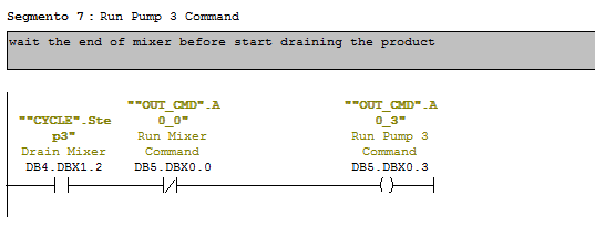
Usually i start writing my cycles from "Step Advance" and "Commands" blocks:

As you notice every step in the diagram has the same number as the step in the cycle, and for every step there is the condition for advancing in the same rung.

Commands:
 
I would like to point the attention on the use of Set/Reset coils for Motor Command.
Even if i prefere to use normal coils instead of Set/Reset, i like even more to see my steps in order from the 1st to the last one.
I know that it's possible and easy to convert the OTL and OTU into a single OTE coil, but for readability i prefere to use one rung for each step and place them in ascending order.
That's why for every output that should be energized more than once during the cycle, usually i use latch/unlatch coils.
Be careful on doing it with finite state machines, because it's easy to make error if the cycle skips the rung that resets the coil.
Notice that in the step #2 it's implemented the condition to start the motor (manual restart + PB pressed). Usually it's a good habit to put a NO contact on the top and an NC on the bottom to refere to the same condition (like Automatic / Manual selector) but here it was used a three state selector, and so i suppose to have 3 inputs.

In the end i usually write the Start - Stop - Init rungs:
As you can notice, to start the cycle it's enough to latch the 1st step, the reset request is satisfied by the cicle stop and the init must reset the commands.
Cycle is enabled by pressing of start PB and stopped by Stop PB, so i called the enable signal "Automatic Mode", so everyone can understand what's going on in the program.
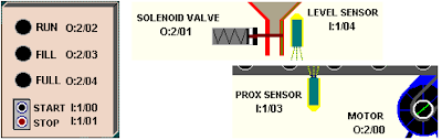
5) Output Mapping
For Outputs, except pilot lamps, i separate rungs in "Automatic mode" and "not Automatic mode", using the second essentially for jogging.
In this exercise it's required the possibility to move the conveyor with a "bypass selector" that is exactly a jogging control for conveyor.(i will add the picture soon... be patient)

6) Exercise file
you can find the exercise solved for RSLogix 5000 here: http://www.megaupload.com/?d=9GXL96L7

Next part here: Simulation

PLC Training: Exercise #2 Simulation with RSLogix 5000

You can find the other parts of the exercise here: http://mestaa.blogspot.com/2011/05/plc-training-exercise-2-solution-with.html

RSEmulate Tutorial:
You can find a good tutorial for RSEmulate 5000 here: http://www.plcdev.com/a_quick_tutorial_on_rslogix_emulator_5000.
Pay attention especially in the last part where it says that for inputs you should refere to local_input[1] and for output refere to local_output[0].

7)Simulation
In test driven development usually it's a good habit to write simulation before the logic, and then test the logic while writing it.
To simulate a real plant just connect the output to inputs, designing an ideal behaviour of your plant.
For example we know that when the motor is ON the conveyor moves and the position of the box changes.
When the box is in a certain position we know also that the Prox Sensor must be ON.
So to simulate that the position increase use a DINT variable to increment when the motor is ON and to reset after a defined value (8 in my case).
Then turn ON the proximity when position is between 3 and 5.
The same can be done with the level sensor, but we have to remember that when the box is full, the level sensor remains ON until the box hasn't moved away from it.
The following is one way to simulate this process.

PLC Training: Exercise #2 Input Mapping

You can find the other parts of the exercise here: http://mestaa.blogspot.com/2011/05/plc-training-exercise-2-solution-with.html
 
1) Sequence analisys and algorithym

Step #1: Waiting for Box in position
Step #2: Box is full
Step #3: Box is moved outside the level sensor
To change steps follow the arrow and the signal that has to be received.
From all steps you must be able to stop the machine if Stop push button is pressed
If the machine is stopped, pressing Start push button will restart the cycle from Step #1

2) Writing the program:
Defining tasks:

those 3 tasks should be in every program
-Simulation
-Map Inputs
-Map Outputs
- There should be an Alarm task also, but in this exercise alarms are not requested.
I gave the name MainProgram to the task that runs the cycle because this is a really simple program, with one short cycle and a start/stop without particular requests.

3)Input Mapping:

I usually map inputs in DINT variables, so i can force them without problems while debugging on the real plant.
Also it makes it easy to change a broken Input without having to change all the program.
Other programmers uses to map Input in UDT data types, with all the problems connected on the  debugging phase the real system when it is ready.

As for the output i usually write an alias tag, because i always use outputs once in all program and with a coil segment.

Next part is here: Cycles and Outputs

PLC Training: Some interesting exercises

I found some interesting exercises about plc programming that cover almost all the topics that a programmer should know.
The document is mainly thought for Allen Bradley plcs users, but it can be useful also for others.
The exercises are:
1) Using simple relays logic to control a motor
2) Using relays logic to control simple sequences
3) Using Timers, Retentive Timers and Counters
4) Using relays logic + everything saw before to control a batch mixing system
5) Using shift registers to determine the position of a bottle in a filling plant
6) Using various modules to control an elevator system.

The pdf  was found on http://thelearningpit.com/lp/logixpro.html, they also sells some kind of graphical simulation to run the plants if you're interested.
 I reccomend to try logixpro simulator (15 days trial) because it can really improve your ladder code with just your time.
You can download the exercise file directly from learning pit website or from here:
http://www.megaupload.com/?d=PIWQA7AS

Databinding #3: binding directly to a Property with INotifyPropertyChanged

Hi,
this is the last part about databinding.
You can find the 1st part here and the 2nd part here
We saw how to bind UI controls on UI elements and on elements that belongs to a collection.
We noticed also that when an observable collection changes(if one item get added or removed), is changes also the UI elements in bind with the collection; the limit of observable collection is that if i change a property in a element inside it, it doesn't update it.
To do this update of property inside elements of a collection, we need to implement an interface, called INotifyPropertyChanged, that fires an event when the property changes, updating all the elements that are in bind with it.

Let's analyse an example:
i 2 tanks, and i have a collection of 2 liquid (liquid[0] and liquid[1]).
Liquid[0] is the content inside the 1st tank, liquid[1] is the content inside the 2nd tank.
I want to change the color (or state) of content changing the property inside the class, and i want that the UI updates the color when it changes of course.
Let's write the new class for the content:


class Liquid:System.ComponentModel.INotifyPropertyChanged
{
public string Name { get; private set; }

private SolidColorBrush liquidColor;
public SolidColorBrush LiquidColor { 
get
{
return liquidColor;
}
private set 
{ 
liquidColor = value; 
this.OnPropertyChanged("LiquidColor");
}
}

public Liquid(string name, Color color) 
{
this.Name = name;
this.LiquidColor = new SolidColorBrush(color);            
}

public void Change(SolidColorBrush newColor) 
{
this.LiquidColor = newColor; 
}

public event System.ComponentModel.PropertyChangedEventHandler PropertyChanged;
protected void OnPropertyChanged(string propertyName)
{
if (PropertyChanged != null)
this.PropertyChanged(this, new System.ComponentModel.PropertyChangedEventArgs(propertyName));
}

This is the implementation if INotifyPropertyChanged.
In the bottom part there is the definition of the event that i throw, and inside the declaration of the property LiquidColor i throw the event every time that this the property changes.
Then i added a method Change, that changes the color with a new one.

Let's define a liquid collection:
class LiquidCollection:ObservableCollection

{

public LiquidCollection() 

{ 

this.Add(new Liquid("Liquid Silos 1", Colors.Aqua));

this.Add(new Liquid("Liquid Silos 2", Colors.Orange));

}

}


Datacontest:
public MainWindow()

{

InitializeComponent();


LiquidCollection liquids = new LiquidCollection();

ellipseSilos1.DataContext = liquids[0];

ellipseSilos2.DataContext = liquids[1];

}


and 2 button's callbacks that change colors to each silos:
private void btnChangeS1_Click(object sender, RoutedEventArgs e)

{

((Liquid)ellipseSilos1.DataContext).Change(colors[i]);

if (i < 10) i++; else i = 0;

}


private void btnChangeS2_Click(object sender, RoutedEventArgs e)

{

((Liquid)ellipseSilos2.DataContext).Change(colors[i]);

if (i < 10) i++; else i = 0;

}


UI Databinding now refers directly to the property that changes:

And we have the UI update when property changes inside the collection.


As usual the complete solution can be found here: 
http://www.mesta-automation.com/Downloads/Databinding3.rar

Next post i'll make a simple project in wpf where i connect an opc server to the UI through databinding.